Search
Filters
Close
Ford Ranger Battery Project

An off topic post today. I have a 1998 Ford Ranger. I’ve had it since I was in high school and its been with me almost half my life.

Today it had a dead battery, a situation I am sure we have all been in. I happened to have a Optima Yellow top group 51 battery that we often use in 3/S cars to save some weight, yet still have plenty of cranking power…

I think you can tell where this is going. A group 51 battery is no way a good fit for a Ford Ranger, especially when its a Group 51R, with its poles reversed, but I didn’t let anything stand in my way and made it work! I feel like if you have that attitude you can do anything you want in life.

6 Speed Performance 3000GT Transmission Rebuild and Transfer Case Rebuild Results

At Rvenge Performance we specialize in 3000GT transmission rebuilds, including its sister platform the Dodge Stealth

We recently finished a Performance 6 Speed Transmission and Transfer Case rebuild and just completed our Q/A Process.

This is a very nice unit that includes a billet bellhousing brace1/2 billet shift fork, a full carbon synchro set, all new OEM seals, all new bearings, reset bearing pre-loads, a replacement 6th gear and slider, new shifter bushing, and a 300m output shaft.

The transfer case included a 300m input spool replacement, a bearings, and a full OEM recall reseal kit

Dodge Stealth R/T Turbo Shop Car & 3000GT Performance

We supply parts and services for a wide variety of platforms and engines, but our passion was ignited by the 3000GT and Dodge Stealth, particular the Turbo AWD Models. 3000GT Performance is in our blood!

Our first car was a 1995 Dodge Stealth R/T non turbo, black on black and we loved it. The styling, the speed, and comfortable GT cruising were a great combination and just made a well rounded car.

Today our specific passion is a 1995 Dodge Stealth Turbo in Galaxy White Pearl. It is where we got our name!

This car has been a labor of love for many years and has the following performance modifications.

3000GT Performance & Strength Modifications

  • Rvenge Performance Built Performance 6 Speed Transmission
  • Rvenge Performance Built Transfer Case
  • Rvenge Performance 3/S Rebuilt Rear End
  • PST 2 Piece Steel/Aluminum Driveshaft
  • Rvenge Performance Coil On Plug Ignition
  • NGK 8 Series 4554 Spark Plugs
  • 99 Headlights and turn signals modified to fit the 2G R/T Stealth Bumper
  • “Oohnoo Bob’s” bell core based sidemount intercoolers and DN hard piping.
  • Fully Polished Intake and throttle body.
  • Large K&N Stainless Steel Intake Setup
  • Fully forged 3.5 liter 6G74 based stroker engine with BC rods and Ross pistons.
  • Redline 5w50
  • Oversized Setrab Oil Cooler
  • High capacity and baffled oil pan
  • K&N HP-1005 Extra Large Oil Filter
  • DR750 Turbochargers with titanium turbines and billet 1 bar wastegates
  • Tanabe Medallion Touring Exhaust
  • BC 266/272 Camshafts
  • 1650cc FIC Fuel Injectors and E85
  • Aeromotive FPR
  • Mishimoto Radiator
  • Samco Radiator Hoses
  • AEM Series 2 + 3.5 Bar Map + AIT + Flex Fuel Sensor + AEM Boost Solenoid
  • AEM AQ-1 Datalogging System
  • Dual AEM X Series Widebands
  • AEM Serial Gauge
  • RPS Street Max Clutch
  • StopTech Big Break System in Front and StopTech Rotors and EBC Red pads in back
  • Tein S-Techs and ECS Struts
  • Leatherseats.com Interior
  • Group 51 Optima Yellow Top Battery
  • Clear Timing Covers
  • Full sound system with Rockford Fosgate 6.75″ Components and 10″ Subwoofer. Pioneer touch screen headunit.

3000GT Performance Tuning

We have tuned 3000GT Performance cars and our Dodge Stealth on the AEM EMS and have experience with Chrome / Flash ECU in the past as well.

Recently we have been upping the boost and the car is in the 550AWHP region at 23 PSI on pump E85. We have hit 100% IDC on the ID1000s and are currently upgrading to the FIC 1650s and the bigger Walbro Hellcat, because we are out of fuel capacity. Stay tuned for some dyno plots! 

3000GT Fuel Injectors and Dodge Stealth Turbo Fuel Injector Recommendations

3000GT Fuel Injectors, this is a set of 1650cc High IMP Fuel Injector Clinic Injectors.

Stock 3000GT Fuel Injectors

The stock 3000GT fuel injectors for the 3000GT VR4 or Dodge Stealth R/T Turbo are rather undersized for the potential of the car and are one of the first things that owners upgrade once they get beyond basic bolt-ons.

The stock injectors are an EV1 style design and are 360cc low impedance injectors. With the brake specific fuel consumption of the Turbo 6G72, injectors in 3/S cars will make close to 1 AWHP per CC @ race gas AFR’s, such as 12:1 and a little less running safe pump gas ratios, such as 11:1. The stock fuel mapping is setup for about 10.5:1 under heavy load and boost.

In practice once you begin to get over the 300AWHP mark it is a good idea to start looking at larger injectors, but first you will need to choice your tuning method as just installing larger injectors on a stock ECU car will make the car run very rich and provide no benefit as you will still hit fuel cut as the ECU perceives load to be near 100% injector duty cycle. This will typically happen as you exceed 15 PSI of boost near redline.

3000GT and Stealth Fuel Considerations

E85 is a wonderful, pump, high octane and high boost capable fuel. We run it in our shop car. One of the issues with it is it requires approximately 40% more fuel due to its stoichiometric ratio being 9.7:1 instead of 14.7:1. Therefore you should plan your injectors being 35-40% larger than if you were going to run gasoline.

Stock ECU / Piggyback Options to manage 3000GT fuel injectors

For a 100% stock ecu your only real option is to use an airflow signal modifying device, such as a MAFT or a SAFC. These devices trick the ECU into seeing less load, but since your fuel injectors are flowing more the net effect is you have a tunable AFR and the ECU will not see fuel cut. For a simple example if you are running 720CC injectors you will remove 50% from the airflow signal.

Consequences of Changing the Airflow Signal

Credit to Chrome ECU for this stock ignition map for the 3/S and ECUFlash for the table representation.

As you can see in the above map the timing is fairly flat above 160 load, which is about when the stock ecu starts getting up over 5-6 PSI of boost. If the ECU perceives less load than this it will add a lot of timing advance. Since you are reducing the airflow signal using a piggyback the ECU thinks the load is less and therefore its important to not run overly large injectors if you are not making a lot of power. 

Practical Limits of 3000GT Fuel Injectors size for the Stock ECU

If you intend to run pump gasoline at any time it would be wise to not exceed 720-750cc injectors. 1000cc injectors are more suitable if you intend to make around 600AWHP on E85, but on  Gasoline you will need more than one piggyback device as many will not remove more than 50% fueling and you are modifying the airflow signal so much that you are likely to have excessive timing, especially at part throttle.

If you intend to ONLY run pump gasoline (no methanol) then you will likely want to target an injector in the 550-600CC range for best performance.

AEM Series 2 or Chrome ECU 3000GT Options

Once you are running a standalone such as the AEM or a Chrome ECU you no longer have to “lie” to the ECU using an airflow modifying device and you can directly edit the fueling or injector size. With a quality high impedance injector you can now run any practical injector, including up to 2150cc for all but the biggest setups out there.

If you are running somewhat older technology injectors that are low impedance you may still want to stick to 1000CC or less or you may have issues holding a stoic idle on gasoline as their low pulse width response may be non-linear.

3000GT Fuel Pump Considerations

Similar to the fuel injectors the stock fuel pump on the 3000GT VR4 and Dodge Stealth Turbo is quite small at about 195 LPH. Just about the time the stock injectors run out the stock fuel pump runs out as well.

The stock wiring also allows for significant voltage drop to the pump, so running a heavy duty power supply from the battery using  some 8 gauge wire and a relay triggering the relay on with the stock fuel pump power wire is a great start and needed for any aftermarket fuel pump.

Once you exceed the stock fuel pump ability a popular option in the past was the Walbro 255, but we have found the newer 450 and 525 series Walbro pumps to be a great and quiet alternative. Keep in mind a large hotwired pump may overflow your stock fuel pressure regulator at idle. This can normally be tuned around, but keep in mind we have sometimes seen 60 PSI at idle using one of the large pumps and the stock FPR. A popular mod is to use an after market fuel pressure regulator.

Conclusion

We hope this article has been helpful and we have some recommendations for injectors below. You may go larger if you are not on the stock ecu.

3000GT Fuel Injectors for Gasoline

300AWHP-500AWHP FIC 650cc injectors

500AWHP-700AWHP FIC 750cc injectors

700AWHP-900AWHP FIC 1000cc injectors or Injector Dynamics 1050cc injectors

1000AWHP 1200cc injectors

3000GT Fuel Injectors for Ethanol / E85

300AWHP – 475AWHP FIC 750cc injectors

475AWHP – 550AWHP FIC 1000CC injectors or Injector Dynamics 1050cc injectors

550AWHP – 700AWHP FIC 1200cc injectors or Injector Dynamics 1300cc injectors

700AWHP-1000AWHP FIC 1650cc injectors or Injector Dynamics 1750cc injectors

1000AWHP + FIC 2150cc injectors 

3000GT Transmission Rebuild and Synchronizer Break-In

A 3000GT transmission rebuild or a Dodge Stealth transmission rebuild is an investment that you will want to protect. There are steps to take to be sure that your transmission rebuild lasts a long time and gives you a lot of joy, shifting the transmission for years to come.

Rebuilt 3000GT Transmission (5 Speed)

Installation Recommendations

A transmission or clutch swap may seem straightforward to many, but there are some things to watch out for.

General Transmission
Rebuild Installation Tips

We recommend picking up the trans from a hoist or engine bar from above, rather than using a transmission jack when possible. We find if you wrap a ratchet strap around the shifter cable brackets it almost perfectly balances the transmission as you lift it up to meet the engine.

On the 3000GT or Stealth six speed you may wish to undo the driver side motor mount and jack up the driver side of the engine as this will give you more angle down and make it easier for the transmission to clear the frame rail.

When the angle is correct the transmission will easily spline into the clutch. If you find yourself forcing it try a different angle and/or rotate the crankshaft using the crankshaft pulley and a 22 MM socket. If you force the trans into place or use bolts to draw it in you will damage the clutch and input shaft, causing poor release.

Clutch Care

The #1 problem that can affect the success of any transmission installation is the proper function of the clutch. If the clutch is in poor condition or the transmission is allowed to hang by the splines during installation then the car can suffer from poor clutch release. This will cause the synchros to be completely overworked and they will rapidly burn up.

If you are installing a new transmission it is a great idea to install a new clutch and either install a new flywheel or have yours properly two step-resurfaced (AWD cars should have .826″ step height). If the clutch step height is too large your clutch may slip and if it is too small it may drag.

Clutch Pedal Adjustment

It is very important to adjust your clutch pedal for the optimal amount of free play. The AWD cars should have .5″ to .75″ of free play at the top. Too little free play and your clutch may slip and too much and your clutch may not fully release. We have a blog post with a detailed video on how to adjust this here.

Clutch Hydraulics

The clutch slave cylinder is a very common wear item and they are very affordable. It is a good idea if you are replacing your transmission to replace the slave cylinder and perform a clutch bleeding to assure great operation. It is the same basic procedure as bleeding brakes.

Please note that FWD and early model cars have a slave cylinder with a 3/4″ bore and the later AWD cars have a 11/16″ bore. You may run either slave cylinder with any year or AWD/FWD, but the 3/4″ bore slave will travel slightly less. You will need to adjust your pedal and you still may not get enough release, so consider running an 11/16″ slave.

Clutch Drag Test

Its very important to perform this safely, but the most sure way to test for clutch drag is to place the car on level ground with nothing in front of you.

Then depress the clutch fully and put the car in 1st gear. Now rev your car slowly to the redline and see if the car tries to creep. If the car creeps at all your clutch is dragging and must be fixed or you will destroy your transmission. We cannot warranty transmissions that are damaged from clutch drag.

Shifter Adjustment

It is equally important that the front to back and side to side action of your shifter is adjusted perfectly. The 6 Speed transmission does not have a front to back adjustment, but on the 5 speed it is important to get these centered to assure proper gear engagement and that you are not causing the shift forks to travel too far, causing damage.

The best way we have found to adjust the action of the shifter is to install the shifter cables on the transmission end and the put the transmission in neutral. Next remove the shifter boot inside the car. Then remove the cotter pin from where the cables attach to the shifter assembly. Loosen the jam nuts on the shifter cables and rotate the turn buckles until the eyelets will slip easily back on the shifter attachment points.

Finally put the cotter keys back and verify the shifter knob is centered side to side and front to back. A test drive will reveal if some minor adjustment is still needed to suit your driving preference.

Fluid Considerations

Traditional gear oil tends to not work well on the 3000GT Synchros in the AWD transmission. This is due to their small oil channels. Traditional gear oils were designed for all brass synchros. They had large oil channels and had gears that did not have needle bearings, but were bushed.

For a 3/S AWD its recommend to run what is typically referred to as a manual transmission fluid (MTF) instead.

Pennzoil Synchromesh has shown over time to be one of the best shifting fluids, but it breaks down rapidly and should be changed very frequently (every 3K) miles. Torco MTF is highly recommended for the Carbon Synchros. 

Redline MTL or MT-85 have been shown to be one of the best all around fluids for the 3000GT transmission. Shifts nearly as well as synchromesh, but will last 10,000 miles or more and provide better protection.

Break-In Procedure

You need to cover your basics, such as careful installation, proper clutch operation, shifter adjustment, and run a quality fluid. There are still some steps to take to be sure your transmission performs at its best.

First Test Drive

Take the car around the block, carefully and slowly shifting, let the car warm up fully. The transmission may feel stiff, but it should not prevent you from shifting or “block” gears. If it does you should verify your clutch is not dragging once again. Bring the car back to your work area and verify their are no leaks, unusual noises and that the shifter feels normal. Its easy to get a wire or hose in the way of the shifter under the hood on these cars, so if anything feels odd check there first.

Second Drive

Now that you have verified everything is working normally its time to go on a longer drive. Begin to work the transmission a little bit harder. Shifting at 3000-4000 RPM is appropriate, but don’t jam it into gear.

It should start feeling smoother and smoother. Synchros are just like brake pads or clutches and will take time to develop a great wear pattern into the metal surfaces. Over the next few hundred miles the transmission should continue to get more and more effortless to shift. It may continue to even improve up to a few thousand miles. 

You should change your fluid after the first couple thousand miles and then go on your regular schedule after that. Keep in mind that these transmissions have no filter, so its best to keep clean fluid in them.

You will see some dusting or material on your magnetic drain plug and this is completely normal. The first fluid change may also show some synchro material particles and that is also completely normal, but should reduce on subsequent changes.

3000GT Transmission Rebuild Conclusion

There are many parts that will wear in as your new transmission passes through its first few hundred to few thousand miles.

Synchros will bed and bearings will wear in slightly. Your gear teeth will wear together. If gears are replaced or your bearing pre-loads are reset your gear teeth will mesh slightly differently than before.

Its important to give the transmission time to wear in before subjecting it to full load. Avoid any launches before you have put at least 500 miles on any rebuilt transmission or transfer case. Avoid redline hard shifting for 500 miles. Your transmission rebuild will reward you with a long life! 

6 Speed 3000GT Transmission Rebuild Part #1

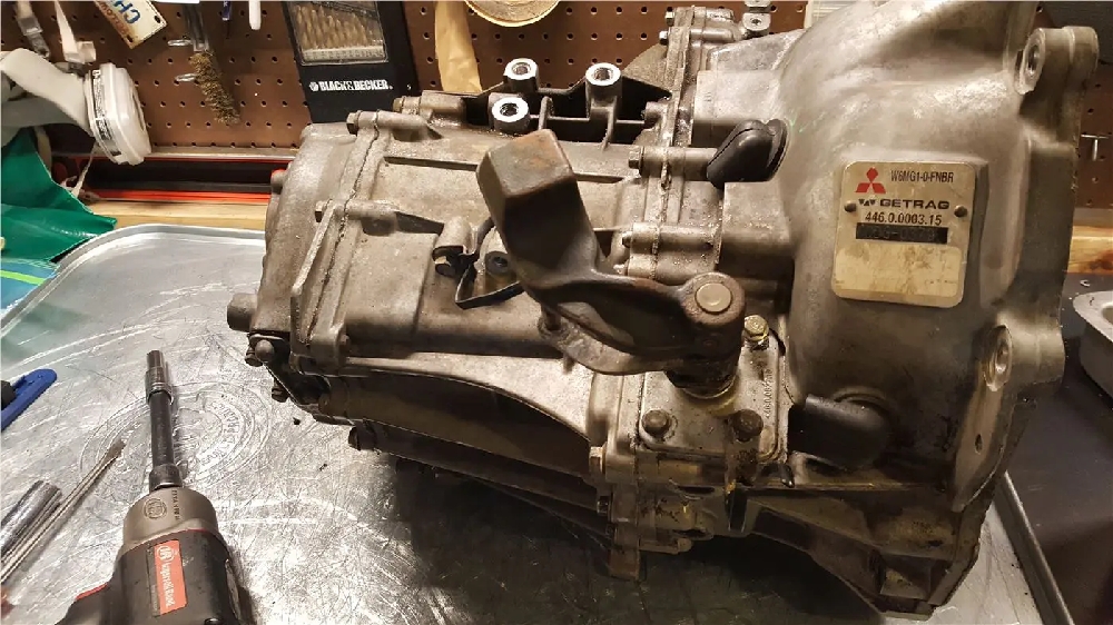
Today we are going to illustrate some of what’s involved in changing synchros in a 3000GT VR4 or Dodge Stealth R/T Turbo. This is also useful for those of you who want to take advantage of our cluster rebuild options.

These are not all the steps we take, but we think they will be helpful. It is a very labor intensive process. Some of the steps are changed to make them more friendly to people with less equipment available. It is still recommended to have a shop press of at least 12 tons, some bearing race/seal drivers, a good set of sockets, some punches, and a hammer. A block of wood and a nice clean place to work is important too.

We may not cover some of the finer details, such as setting bearing pre-loads, but we do have some videos illustrating some of that on our youtube channel and in our other blog posts.

Before I get started, please know you do not need to be rough on one of these transmissions to get it apart. If you find you are really having to handle something roughly you need to stop and think. Check for missed bolts, dowels, things slightly out of mis-alignment, etc.

These all don’t necessarily need to be in this exact order, but use some common sense.

Step 1

The first thing I do is drain the transmission completely by turning it up on its end case and then only an ounce or two of fluid will be left inside. There’s nothing worse than opening the case and having it spill all over the place.

Step 2

If your trans is really dirty on the outside take it to the local car wash and use the engine clean setting on it, blast off as much dirt and grease as you can. The cleaner it is when you take it apart the less stuff falls in it. Think of an open trans as an open wound. Keep it clean. Put it back together sitting loosely if you have to leave it sit out.

Step 3

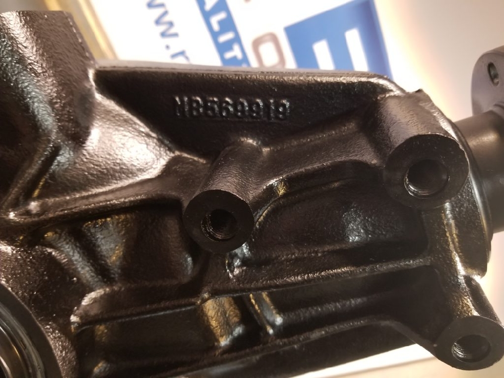
Go over any bolts that look questionable. The trans mounts were super tight and my impact really got a workout. Luckily only one pulled the threads out, two I could save. 

Trans mount bolt holes are 12mm by 1.25 pitch.

Two cleaned up great, one had the threads come out completely.
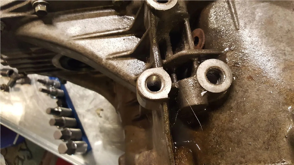
Heli-coiled:

If you need to repair a t-case hole I STRONGLY suggest using a drill press to be sure the hole is plumb. Very easy to get one in at an angle and that is difficult to repair.

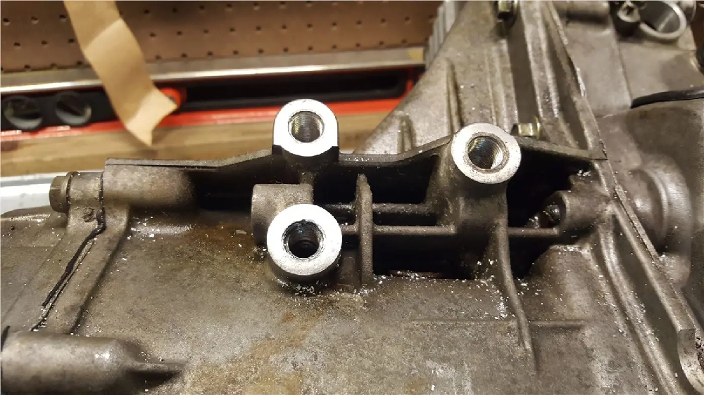
The block to trans holes should be chase as well (also m12 by 1.25)

I did the t-case holes as well, they are m12 by 1.75. I also did the side brace mounts which are m10 by 1.5 and the slave cylinder mount, which is m8 by 1.25. Use lube when tapping. Clean the threads when done. I like to do all the bolt holes before starting because you will know if the case has serious damage and any metal mess when get cleaned up before cracking the trans open.

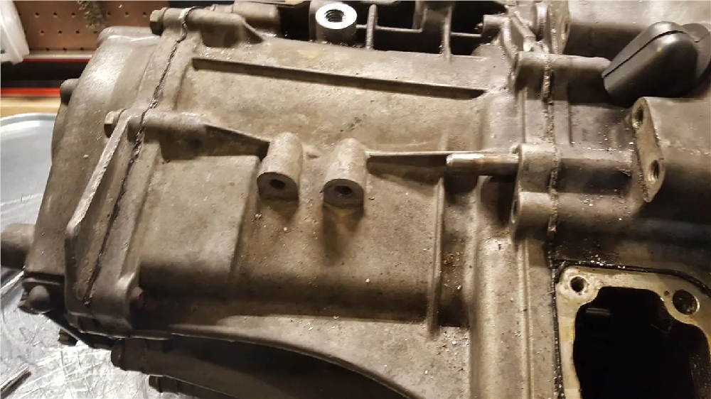
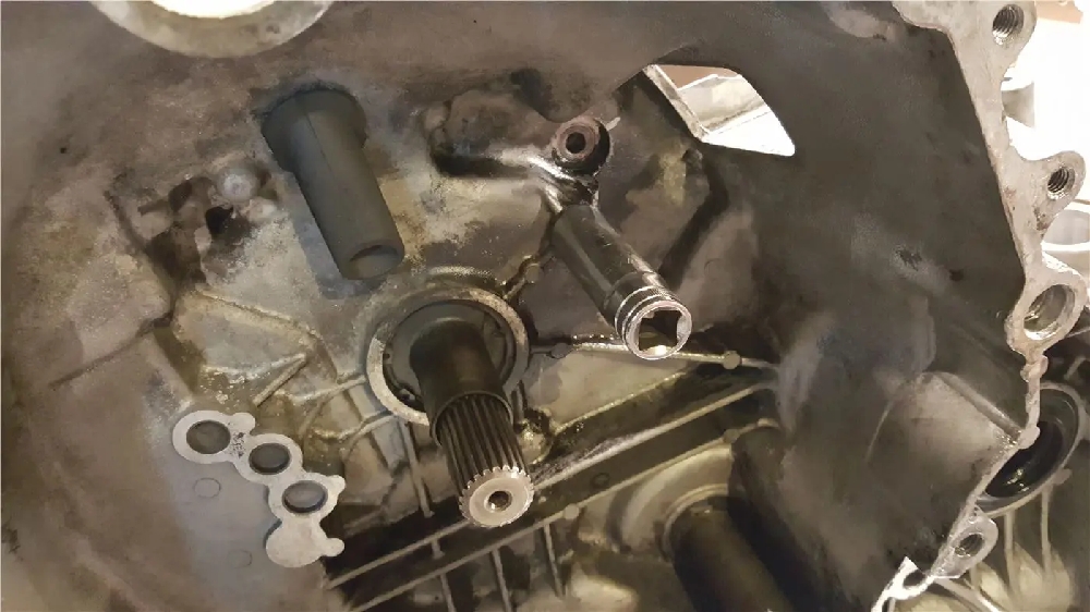
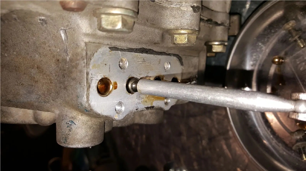
At this point you want to remove the shifter detents, reverse lockout, and the reverse light switch:

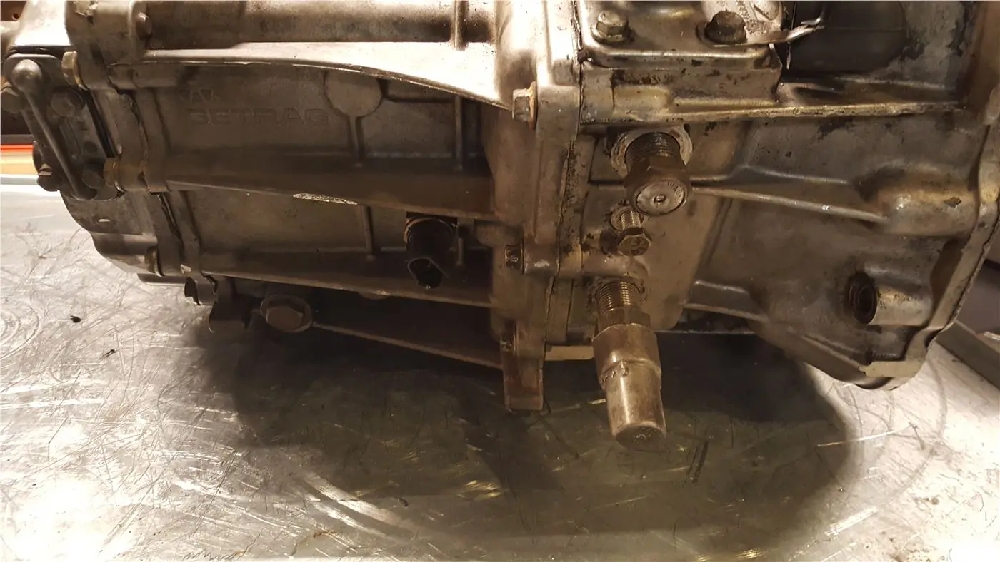
You will need a 24mm wrench for the big can looking thing, which is the reverse lockout. You will need a 13mm socket for the shifter guide above that and you will need a 22mm socket for the shift detent above that.

The reverse switch is 24mm.

All of these parts are set with blue loctite, so they may take some effort to remove. I have seen the threads worn quite a bit on these when removing them sometimes. Work them in and out and use lube if they get stuck. The trans really isn’t all that thick there.

Once that is out of the way, remove the 4 bolts holding the shift tower in.

Remove the two bolts holding the L-shaped bracket that moves the shifter up and down (side to side in the car, not pictured).

You will need to carefully work the square shifter base off the trans.

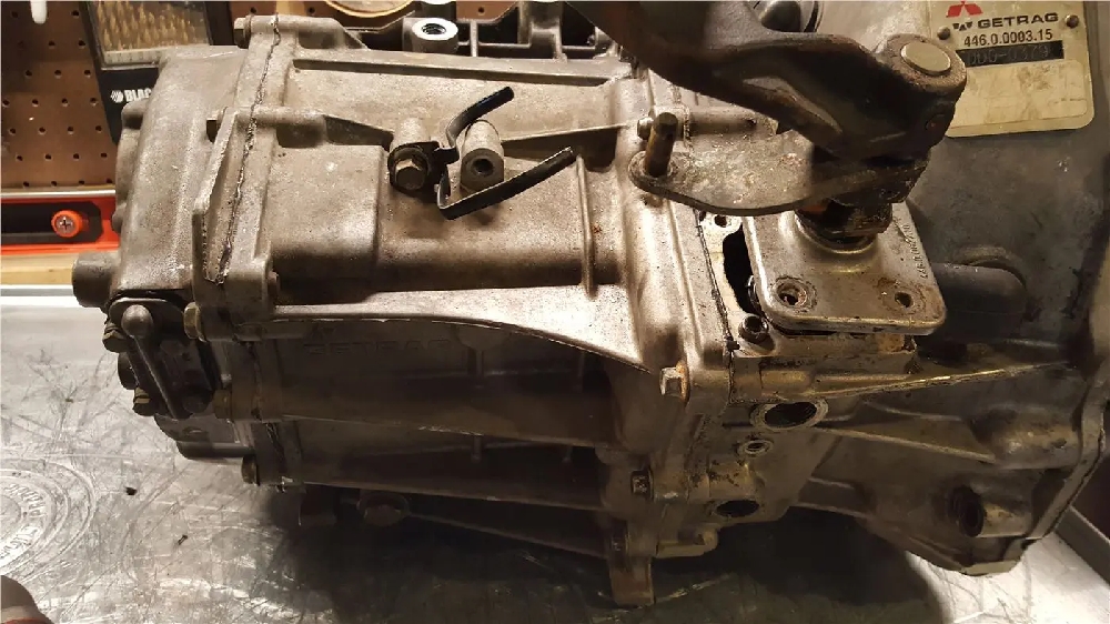
Try not to use a chisel here, it may damage the mating surfaces. Try to swiftly pull it up and snap it apart. If you must use a chisel, be sure its very sharp and be careful!

It will be rtv’ed if the trans has been apart before or will have the anaerobic sealant on it if its never been opened or someone used the correct stuff last time. It will be tough because there are two dowels, so you can’t twist it. I don’t advise being too rough on it because there is a spring inside you can damage. You can use a small chisel and work it loose a little at a time on each side. Be careful not to mar anything up. Any high spots will need to be filed down and any low spots are potential leak spots. Small nicks don’t cause problems if they are sanded smooth.

Carefully work this piece up and out:

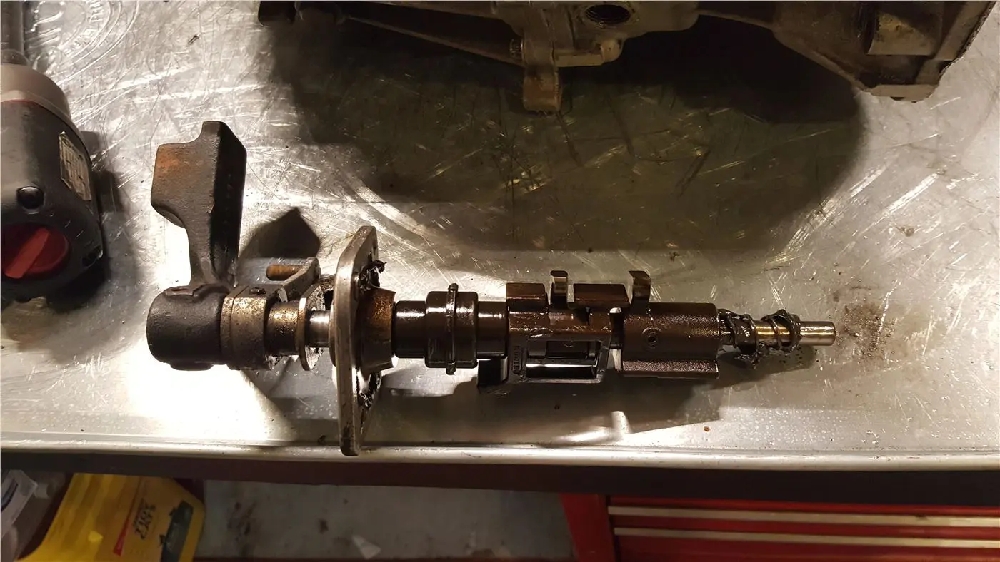
The spring will usually fall off, this one stayed on because it was greased recently.

Now we are moving on to the dowels and bolts…

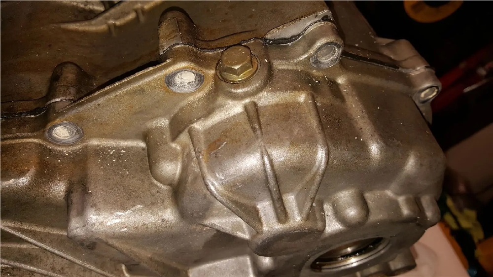
Note the dowel pin. I always hammer them out before pulling the case apart. This keeps you from beating on the case and damaging the shift fork rails. The factory did us a favor and gave an access hole:

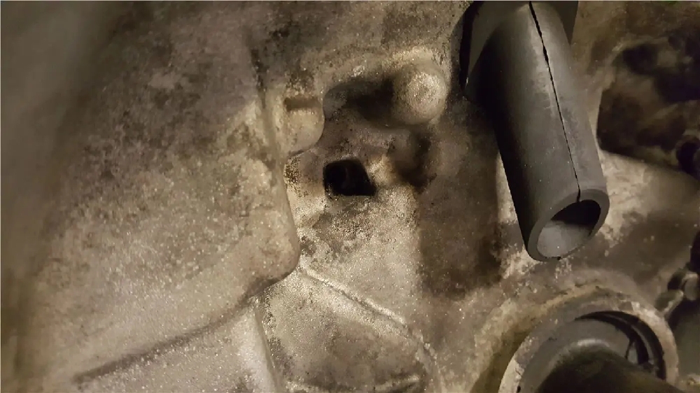
Tap it out with a punch.

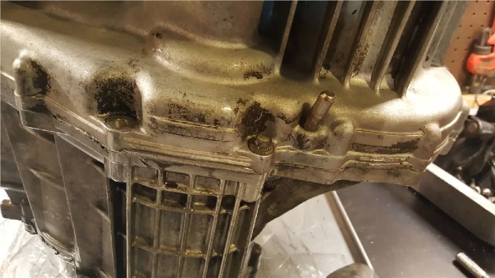
The six speed has a bellhousing bolt INSIDE the bellhousing. if you can’t see it the clutch fork is in the way….

The bellhousing bolts are 10mm headed.

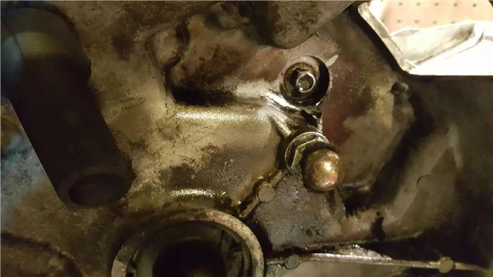
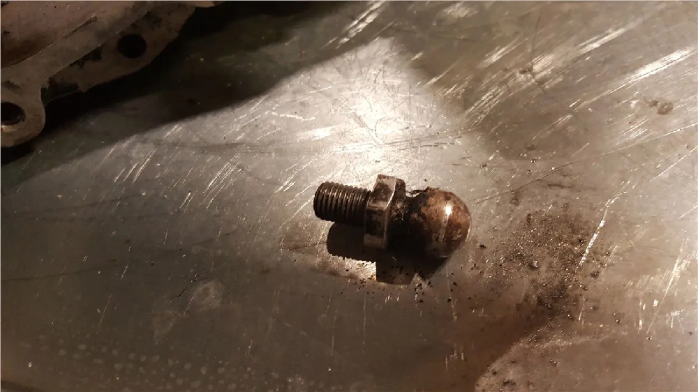
Remove the clutch pivot ball because its probably worn out. (17mm)

If your ball looks like this replace it. It will impact your clutch pedal performance.

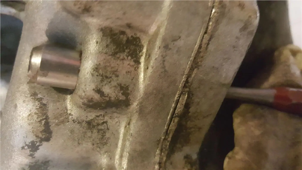
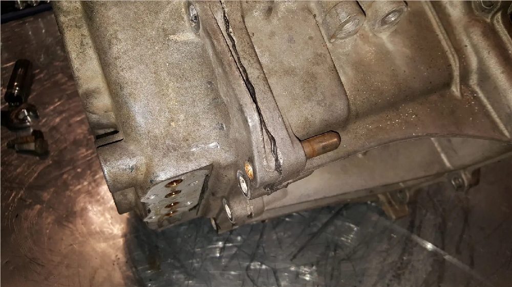
There is another dowel on the other side:

Remove ALL the bellhousing bolts:

Depending on how much RTV that may have been used it may be hard to get the bellhousing to come off. Tap on the safe spots (they are rectangular spots on a couple ends of the case) until you get it to crack loose. Use a rubber mallet or block. Work your way around evenly. Don’t be tempted to put a chisel in there… Do not beat the crap out of it. Try another side if you can’t get it loose. Make sure you have ALL the bolts out. Lift it [B]straight up[/B] to avoid damaging the input shaft internal seal.

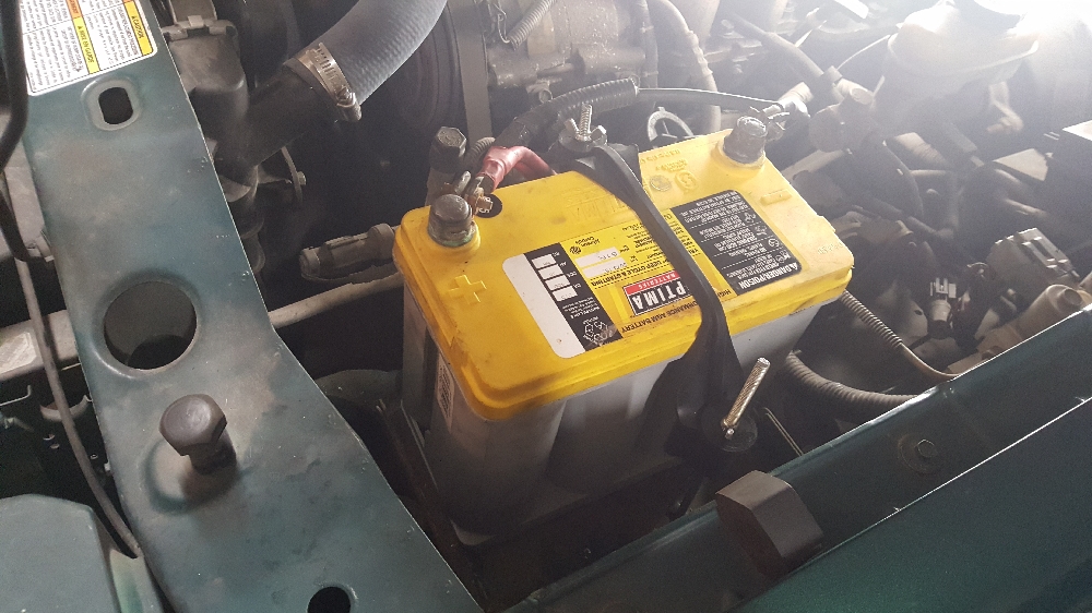
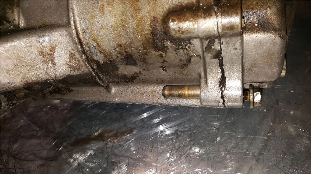
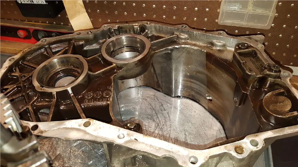
You should be greeted with this:

A filthy bellhousing. Notice the clean line?? That is where the new fluid reached… No one can say synchromax doesn’t have enough detergent… that was just sitting still a couple weeks.

Use mineral spirits and brake cleaner to clean things up. Try not to get harsh chemicals inside the input shaft bearing. Oil all the races when its cleaned up and the inside of the input shaft bearing. You don’t want the input shaft bearing to dry out as it is unavailable now, except the last few NOS ones.

Next we will separate the midcase. 

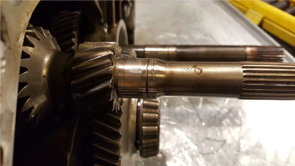
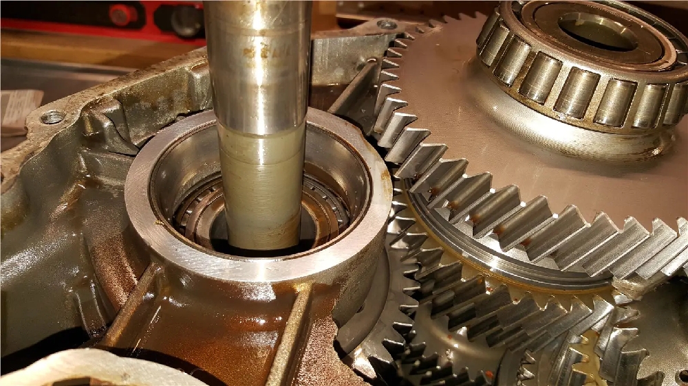
Inspecting the input shaft reveals some pretty bad damage to the area the input bearing rides. I would not use this as is because its going to make a lot of noise and destroy the input bearing. Careful inspection of the input bearing revealed it was okay.

Remove the input shaft plug by either very carefully prying it out or driving a sharp pic through the center and prying it out. The pick method is safer to the transmission case, but if you are very careful sometimes you can save the plug if you pry it out from the edge.

You need to remove the 4 bolts holding the detent plate in now. Don’t remove them completely, because once you break the sealant loose springs make it want to pop out.

Carefully pry the plate loose, try not to damage the sealing surface. 

Place a magnetic tray under the detent plate if you have one to catch things an finish removing the bolts.

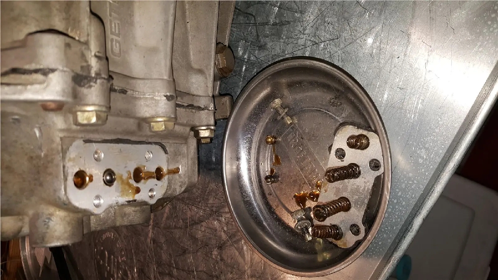
Use a magnet to pull out any detent balls that stayed in.

Remove all the 13mm headed bolts (The German heritage of the trans shows through since this does not use Japanese spec bolt heads, sometimes they are 10mm, probably rebuilt by Mitsu) Leave the side facing bolt in, that holds the reverse idler bracket in.

Knock out the dowels:

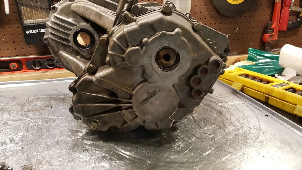
With all the bolts removed, flip the trans so the end case is on the bottom and using a mallet knock it loose from the sealant. I usually try hitting the front diff area as it seems to come apart easily then. Use a RUBBER Mallet. Do not beat on it, this area is weak.

You now need to slightly twist the mid housing so it clears the 1st gear and then pull up:

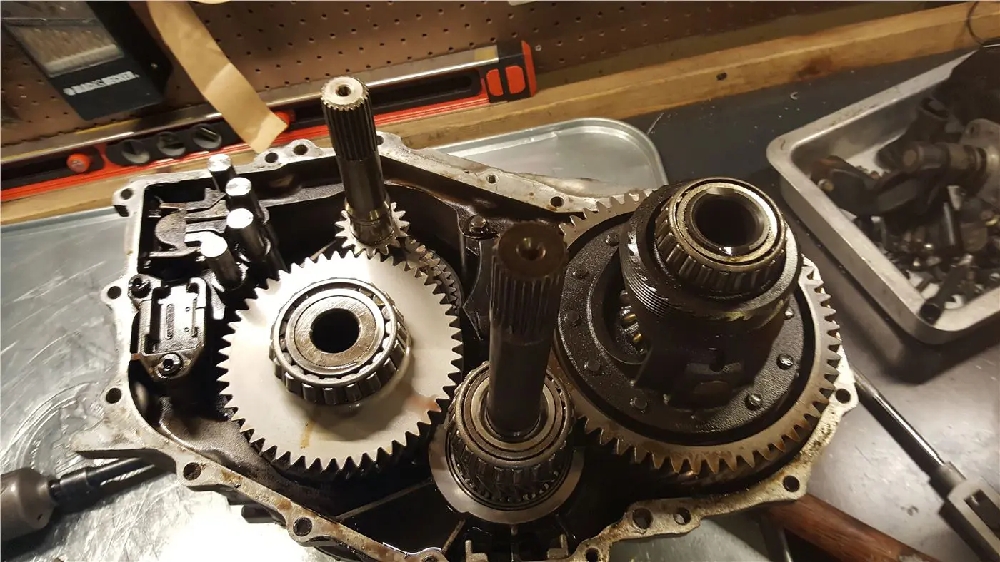
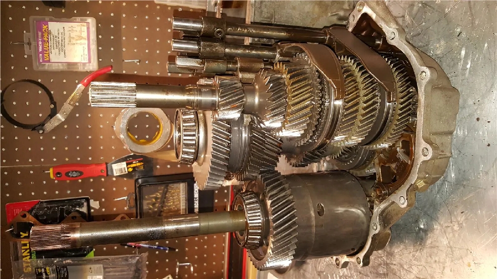
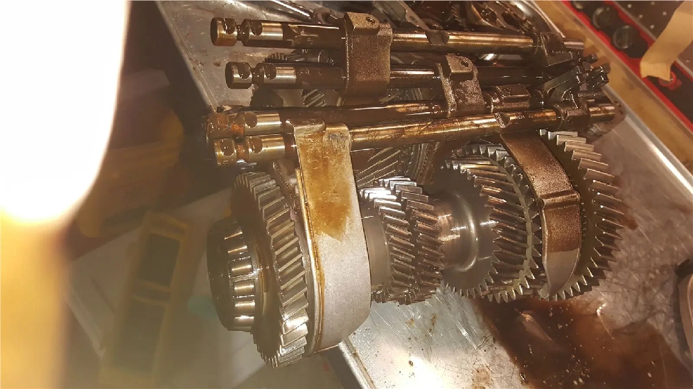
The mid housing will come out now, this trans is VERY dirty! It has had a vcu failure.

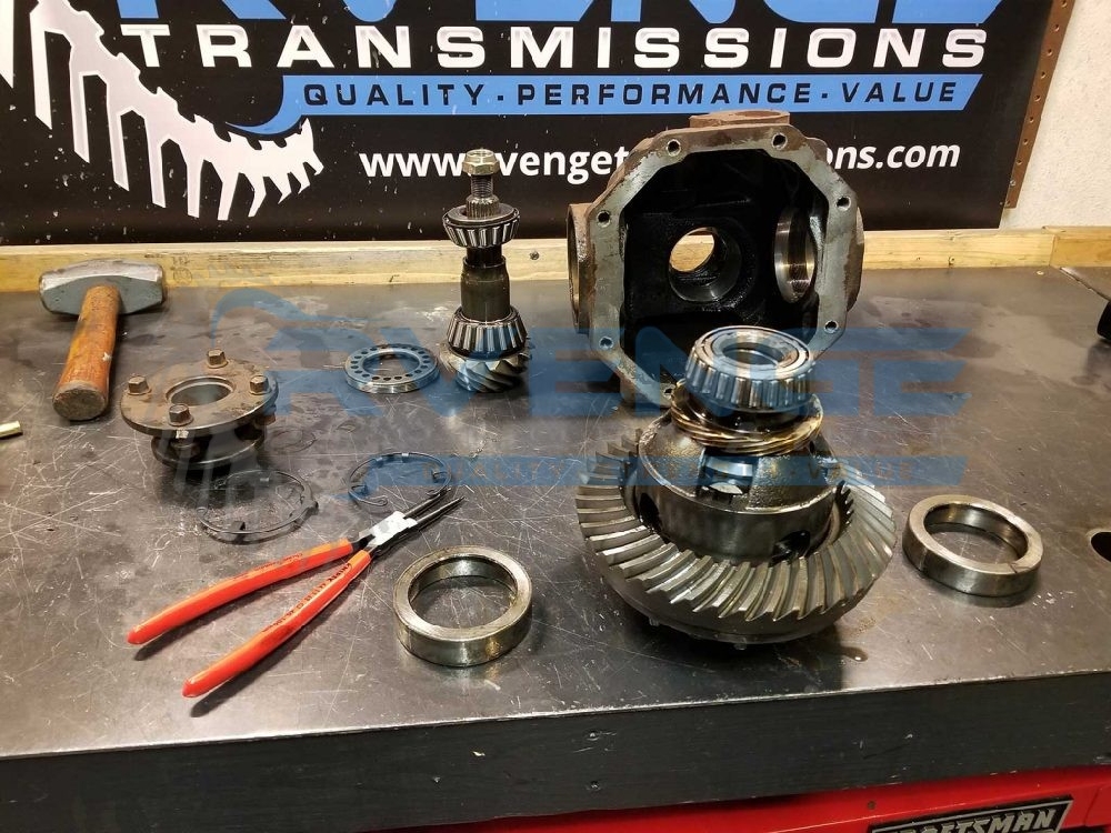
You should now see the input shaft, counter shaft, vcu/center differential assembly, and the end case.

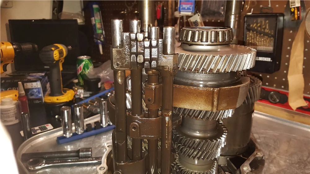
Engage two shift rails/gears at once so the input shaft can’t spin:

You need to use a 12mm allen socket to remove the input shaft bolt. Its 70 ft/lbs and has loctite, so an impact wrench makes it much easier.

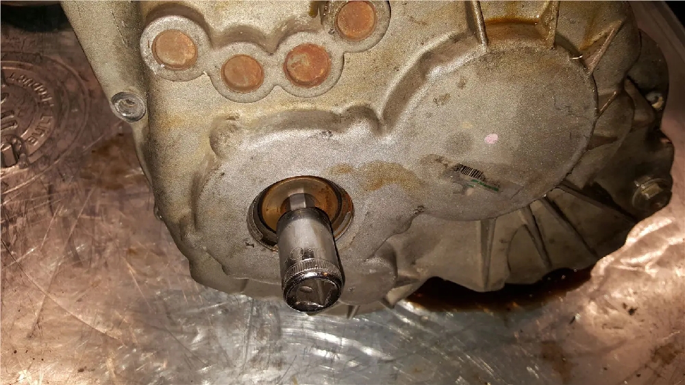
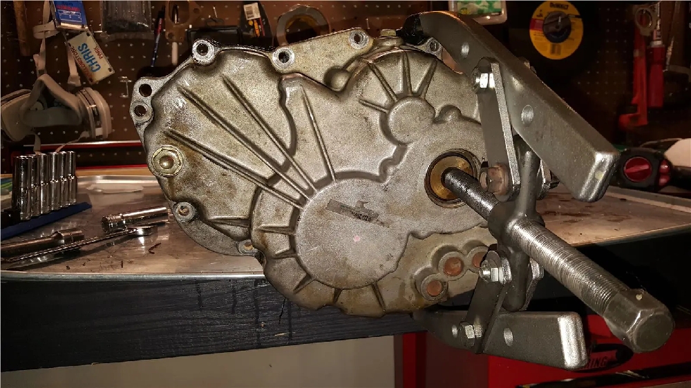
Some people hammer these out, but I like to press the input shaft out of the bearing in the end case. I use a fairly large puller. Loose the bolt a few turns. Press it loose, then loosen it more turns and press it all the way. not having the bolt all the way loose at first will help prevent damaging the threads in the input shaft. I have never found one of these super tight. If you have a big enough press you could do that, but I like this way because nothing is trying to fall out.

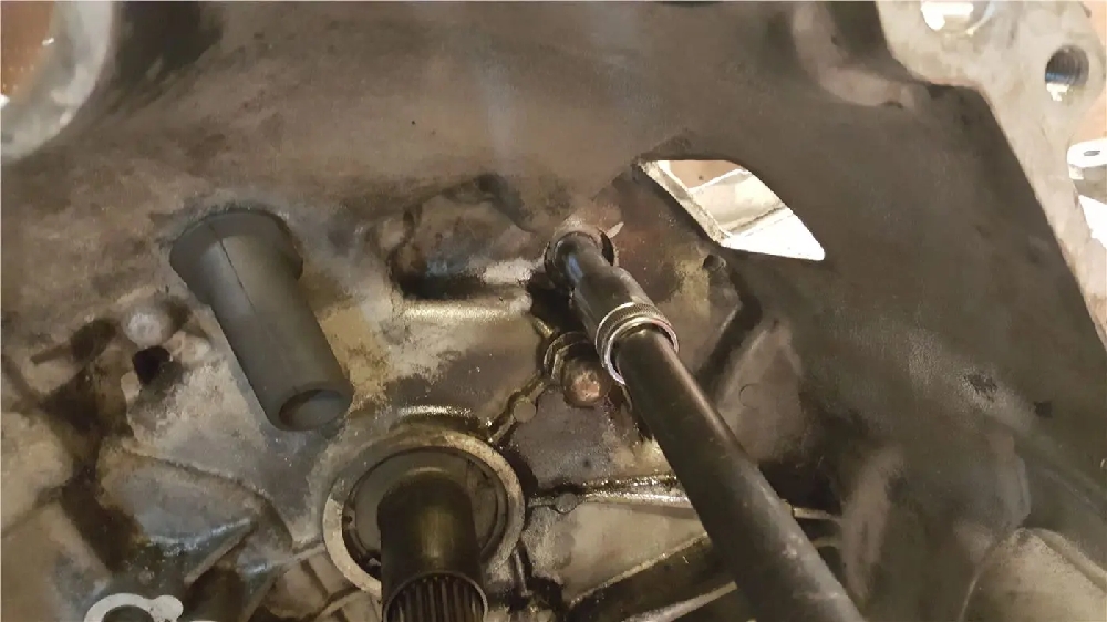
You can see the bolt removed now and the input shaft is pressed all the way through:

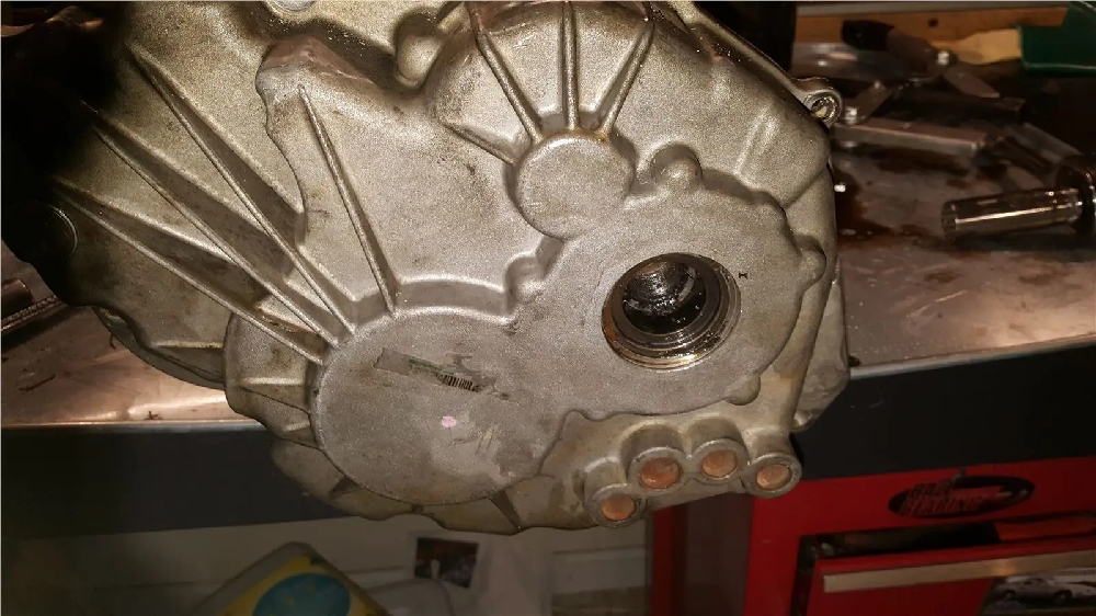
You will now find the shift rails are bound up, keeping the case on. Wiggle the case off the shift rails.

Pull the case off.

Part #2 Coming Soon! 

1650cc HighZ FIC 3000GT Fuel Injectors

Today we are beginning testing of 1650cc high z FIC fuel injectors on our Dodge Stealth Turbo shop car. For a full list of mods please visit our post on it here.

We wanted to share a un-boxing video and talk about some of the benefits of the new 1650cc high impedence, stainless steel internals, bosch based, injectors from Fuel Injector Clinic.

We are upgrading the car from 1000cc injectors to 1650s because we are at 100% IDC on E85 at about 25 PSI and we need some headroom for more boost!

We offer these injectors for many applications, so if you do not see your application on our site please inquire. For 3000GT or Dodge Stealth FIC 1650s click here.

NEW

We have an installation post and video of a set of 1650 cc 3000GT injectors!


Sample AEM Injector Latencies for these:

Sample Haltech Elite Settings


FIC 1650cc Fuel Injector Install for the 3000GT and Dodge Stealth

Today we are in part 2 of our FIC 1650cc Injector series. In part one we did an unboxing video. In part two we will show how to install these FIC 1650s, or any fuel injector in a 3000GT or Dodge Stealth.

This video may also be helpful for those wanting to replace the spark plugs or wires on a 3/S or even to run a compression check. One of the major steps is removing the intake plenum, which is common to many 3000GT maintenance procedures.

For this process you will need approximately the following tools:

  • 3/8 Drive Ratchet
  • 3/8 Drive torque wrench would be nice to have, plenum bolts are 13 ft/lbs.
  • 10mm Socket
  • 11mm Socket
  • 12mm Socket
  • 13mm Socket if you have any aftermarket bolts.
  • Allen sockets if you have any allen bolts.
  • A small quantity of motor oil
  • Clean shop rags

We hope you enjoy our video!

Injector Battery Offset / Latency Settings for the AEM EMS Series 2

For help on setting injector battery offset please view this Battery Offset Guide

3000GT / Dodge Stealth Coil On Plug Kit Installation and FAQ

We are excited to announce our coil on plug kit we have developed for the 3000GT and Dodge Stealth Platform. This kit will help take your ignition into the modern era, using easily replaceable parts and eliminating many expensive / hard to get Mitsubishi specific parts.

Features

  • Mil-Spec wire, color coded for each cylinder. Long enough to run 3 wires to ECU for sequential fire.
  • High quality sealed coil connectors.
  • Included ring terminals and heatshrink butt connectors
  • New Denso or Delphi “Smart Coils” with integrated ignitors, proven to over 1000AWHP. Modified to fit stock plug wells.
  • High Quality Plenum spacer that will not melt (this is needed for rear coils to clear a stock plenum) New, longer allen bolts included.
  • New Coil Bolts and Spacers
  • This should be run fully sequentially on a standalone ECU or waste spark. Dwell settings are critical if running waste spark or the coils can be overworked.
  • Works with stock type/size spark plugs like NGK 4554.
  • Eliminates stock coils, stock ptu, and stock type ignition wires. No ignition amplifier is needed for all but the most insane setups. We are currently running 25 PSI on E85 with a .028″ gap with no blow out

Solder vs Crimp Connections

Despite what common sense would say, it is actually preferred to use high quality crimp connectors over solder. Solder creates a brittle spot in the wiring, which is why you will never see it used on professional race harnesses. The other big issue is the stock wire gets very corroded over time and this causes the solder joint to be poor or hard to make. Sanding the wire can remove the corrosion, but its still better to crimp. For this reason this kit contains heatshrink/waterproof butt connectors to make installation easy.

Requirements

We have really tried hard to keep this as a very affordable kit, that will fit the most setups, so you will need a few things depending on your setup and skill level.

It is a good idea to have a simple coil hotwire. This is similar to a fuel pump hotware and will use a relay trigger by the stock coil power feed to take power directly from the battery for maximum coil voltage.

2 Plenum gaskets, one below and one above the plenum spacer.

Some basic electrical ability.

10mm, 12mm, #5 allen key, basic hand tools.

Wire stripper and crimper.

Electrical tape and/or heat shrink tubing.

Installation

We will try to provide easy to follow steps for this installation, but it may vary depending on whether you are running sequential or waste spark and how you wish to run some of the wires. We will be honest and say this is not a paint by numbers or detailed step by step installation, but we will do our best to outline the steps and also answer questions you may have.

This installation will require cutting the engine harness near the ptu and coils because certain connectors are not available to make this plug and play. If you are not okay with this feel free to seek out a different wiring solution, but it may be the only way.

To get started please find a clean and safe work space to layout all your new parts.

  • 6 Coils
  • 6 Wire harnesses
  • Coil Standoff bolts and spacers
  • Plenum spacer and bolts
  • Crimp and ring connectors

Step #1

Remove your stock plenum and enough intercooler piping to have room to work. Insert shop towels in any open intercooler piping, turbos, and the six plenum holes. Remove your stock plug wires, coil pack assembly, and ptu. This will vary depending on your setup, but you should be presented with this:

Step #2

You will need to remove the studs on the ends of the lower intake. The easiest way to do this is to simple thread on two of the nuts you had used before and jam them together. Then undo the top nut and the stud should come out. Clean any aluminum burrs or dust that appears.

Step #3

It is a great idea to replace your spark plugs at this time. We recommend either a 7 or 8 series (or colder) NGK copper spark set, depending on your power level. Gap the plugs to .025 to .028 depending on your power levels. We are running .028 on our 550AWHP car.

Step #4

Remove the three center bolts on each valve cover that are next to the spark plug holes. These will be used for the bolts that hold the coils down. They have a 10mm head and should not be very tight. If your valve cover gaskets are leaking its a great time to replace them.

Step #5

Test fit and start installing your coils. The coil will slide down the spark plug hole and click into place. The power plug should face the driver’s side. Place the aluminum bushing under the coil and slide the bolt with lock washer through the coil hole and thread into the valve cover hole. There is a rubber gasket inside, so be careful to get the bolt through it and into threads without cross threading. Lighly torque it down until just past snug for each coil. Your coils are now installed.

Shown in the pic is part of step #6. The coil harnesses have been routed on this car.=

Step #6

Begin running your coil harnesses. Each cylinder has a different color signal wire and different lengths. Please use the following colors for the trigger wire as each harness is a different length:

  • Cylinder #1 (front near timing belt): White/Purple 28″
  • Cylinder #2 (rear near timing belt): White/Gray 40″
  • Cylinder #3 (front middle): White/Green: 24″
  • Cylinder #4 (rear middle): White/Blue: 72″
  • Cylinder #5 (front near transmission): White/Orange 72″
  • Cylinder #6 (rear near transmisssion): White/Yellow 72″

You may snap in the connectors, please note they are a very tight fit and can be hard to take back apart, leave enough slack that you can remove the coil for future spark plug changes.

Step #7

Each coil has 4 wires going into it.

  • Black – ground. Either ground at the coil harness or to a clean spot on the cylinder head or similar.
  • Red – This is 12 volt ignition switched power. Either run this to the stock power wire that used to go to the OEM coil pack set or use a coil hotwire and run it from there. It just needs to be 12 volts that is only on when the key is on.
  • White with stripe – This is the ‘trigger’ wire for the coils. These are smart coils with integrated igniters, the ecu need only send a signal to these wires and the coil will fire.
  • White with gray stripe (in some instances white with green stripe, 2nd pin from the top of the connector), tachometer reference. 3 are used from one bank for waste spark and 6 for sequential spark.

Decisions

At this point you need to make some decisions. Are you going to run sequential or wasted spark?

Sequential

The coils may last longer when run sequential and you have some more options with aftermarket ecu’s. Dwell is not as critical in sequential either, as the coils will have more time to rest between duty cycles.

If you run sequential you will run cylinder 1,2,3 to the stock trigger wires on the ptu harness. Cylinder 4,5,6 will have to run to your ECU. The provided wire is long enough to accommodate running to the stock ECU location. You will have to locate 3 un-used outputs on your ECU and modified your calibration. We have provided an example for the AEM Series 2 ECU below.

AEM EMS Series 2 Sample Ignition Output Configuration

  • Cylinder #4 Pin: 91 (Year 91-93) / 62 (94-97)
  • Cylinder #5 Pin:82 (Year 91-93) / 53 (94-97)
  • Cylinder #6 Pin: 85 (Year 91-93) / 56 (94-97)

AEM EMS Series 2 Sample Calibration Changes

Below is a screenshot of what is needed to change the AEM ECU to run fully sequential ignition with your smart coils.

The input change is the coil configuration. The injectors panel may not look like yours if you aren’t running dual widebands.

Dwell Settings

Here are sample dwell settings. It is better to run only slightly more dwell than needed as the duty cycle increases with dwell and therefore coil life may be impacted. We have run the below dwell for a season with no issues and it is similar to Denso specifications.

Haltech Example Settings

Dwell for Chrome/Flashable ECUs

A good place to start is shown below. The stock dwell settings may overheat the coils and cause a misfire.

With a waste spark configuration you will run the trigger wires in similar pairs as stock.

  • Cylinder 1 & 4 will go to 1 & 4 ptu trigger wire
    IB1 is black/blue wire
  • Cylinder 2 & 5 will go to 2 & 5 ptu trigger wire
    IB2 black/white wire
  • Cylinder 3 & 6 will go to 2 & 6 ptu trigger wire
    IB3 brown/red wire

*colors *may* vary, verify by comparing to pinout shown on PTU

Ignore the yellow wire, the orange will go all the way to the ecu on production kits.

Dwell Settings for Chrome ECU

Below are some sample dwell settings for Chrome ECU. It is particularly important that you do not run more dwell than needed in a wastespark configuration as the coils will be firing twice as often.

Power and Ground Wire

No matter whether you run sequential or waste spark you need to run all 6 power wires to a switched 12 volt source like the stock coil power wire or your coil hotwire power. You will also need to run all 6 grounds to appropriate grounding connections. How you do this is up to you. We have supplied enough wire you can either just run all 6 sets and join with the feed wire or combine each bank at each head and run a 10 gauge wire from there to the power. As long as each coil gets 12 volts and ground when the ignition is ok it will work. Included ring terminals make it easy to attach the ground to a bolt on the heads.

Power and ground wires shown on left. Rear bank similar.

Plenum Installation

You will need to remove the studs on each side of the lower plenum to use the included longer bolts. Put two m8 nuts on the stud and jam them together, then the studs will be able to be backed out.

You may find that the longer front bolts may get difficult to turn towards the end on your first install. You can tighten and then back out a few times and it should cleanup/cut a few more threads in the lower plenum or you may use a m8 by 1.25 tap. This was done because the next shorter size bolt does not get enough thread engagement and this is critical to ensure you can tighten your plenum over time without stripping the lower bolts.

Testing and finalizing installation

After carefully making and insulating all connections it is time to test your setup. It is not a bad idea to lay all 6 coils up on the top of the lower intake with a spark plug in each and crank the engine over (remove any rags from any open holes and be careful!).

You will then be able to confirm all 6 coils are firing. They will each fire one at a time in sequential mode or 2 at a time in waste spark. If any are not working be sure the plug threads are touching a ground source. If it still doesn’t fire you need to double check your wiring as you will have a dead cylinder after installation.

Once you have confirmed all 6 fire you can re-assemble your car, make any changes to your ecu you haven’t made yet and try a start. The car should run normally and be smooth without any misfire. If you have a misfire locate the problem before a road test. At this point it is good idea to gradually apply more throttle until you are sure you have strong spark and now you are done.

Tachometer Wiring

The latest version of our coil on plug kit for the 3000GT / Stealth platform utilizes the tachometer reference of each smart coil. The tach wire is the 2nd one from the top on the connector and is normally white/gray striped.

Sequential Tach Output

For sequential operation tie all 6 tach reference wires into the stock white tach wire.

3 wires from both front and rear subharnesses with the stock ptu tach output wire wire shown on the right.

Wastespark Configuration

Since each ignition event in a wastespark configuration triggers 2 coils you will want to only wire 3 of the tach reference wires to the stock tach wire. They need to be one from each wastespark pair, 1,3,5 (all three front banks for example).

Coil Cover Notes

To install the front coil cover may require slight pressure downward. This will press against the ears on the coils, which will not hurt anything and over time the coil plastic ears will deflect just slightly and make installation easier. If a custom prefers he could trim the ears.

For the rear plates the ears on the coils need trimmed to clear the plate, there is just not enough room otherwise. We have also heard one report of the rear plate contacting the throttle body and needing the logo section trimmed off, but we aren’t sure what was different about this car.

Success

You may now enjoy your new coil on plug setup! The car should pull strong and have a lot less clutter underhood. You may be able to run a larger spark plug gap than you could before.

Optional coil cover plate shown. At this point you may want to pickup some Techflex wiring loom. There are too many potential options for us to include it in the kit.

3000GT Rear End Rebuild Results

In this blog post we want to cover the results of a 3000GT rear end rebuild we recently performed. This rear differential from a 6 speed 3000GT VR4 needed a rebuild for many reasons. It was rusty, had excessive backlash, and the seals were leaking.

We had a core in stock and rebuilt it on an exchange basis with our customer. If you are interested in this service please purchase our rear differential rebuild service here.

Rear End Importance

The rear end on a VR4 or Stealth R/T Turbo is an often overlooked, but critical part to your driveline. Up to 55% of the engine power in an AWD 3000GT or Dodge Stealth is transmitted to the rear end through the transfer case.

Driveline clunks may originate from excessive backlash in your rear end. As part of the rear end rebuild process at Rvenge Performance we make sure our units leave the shop in like new or better condition. This includes setting backlash, pinion pre-load, and carrier pre-load back to factory settings.

Along with this we verify the gear tooth pattern and replace any bearings that show wear. We also replace the seals with brand new OEM Mitsubishi seals because they last the longers and paint the rear end a semi flat black to prevent future rusting.

First Steps

The first step to a rear differential rebuild is to disassemble the unit and fully inspect it. Next we put the unit in a chemical bath that removes all the rust and brings the rear diff back to as cast condition. In our opinion this is superior to sandblasting as it doesn’t change the texture of the material, but either are suitable methods.

Units usually start out looking like this or worse.

Rear End Rebuild Continued

Next we remove the carrier and fully break down the rear end. This is the only way to properly inspect the bearings. The ring & pinion receives a full inspection and we take a gear tooth pattern check. We check the pattern before removing the carrier to get an indication of how well the rear end was setup before.

We have the correct tools, including the factory spanner wrench to properly remove and set the side carrier bearing pre-load (not pictured)

The chemical de-rusting soak takes 1-2 days. Even the rustiest steel returns back to an as cast condition. At this point the unit is cleaned again in the ultrasonic tank and then finally cleaned in clean solvent to prevent rusting and remove and water based liquid.

Rear differential bearings that show wear are replaced because they are critical to the function of the re-end. Pinion pre-load is set. The carrier assembly is re-installed, backlash is set, and the carrier bearing pre-load is set.

Final Results

The completed unit, all setup perfectly and painted. Quality sealant, the “Right Stuff” is used to seal the cover to the diff. OEM axle and pinion seals are always used for OEM life and leak free performance.

A factory finish you can be proud of.

This 3000GT rear end rebuild is ready for another lifetime of trouble free, clunk free, service.

3000GT Rear End Rebuild Conclusion

At Rvenge Performance & Transmissions we don’t believe in just fixing your driveline parts. We believe in making them look and function like new or better. If a part is 50% worn out we don’t leave it in to get the remaining life out of it because a customers best return on investment is to bring whatever we do back to 100% condition, to ensure a new lifetime of service.